


PLA33
BMR is a Czech company, inter alia, a manufacturer of equipment and electrical network surveillance system. The basic solution are multifunctional analyzers PLA33 series occurring in many variations. From the simplest offering only the display of the measured parameters (as a substitute for measures of analog), to advanced communication via RS485, internal memory, and programmable logic outputs.
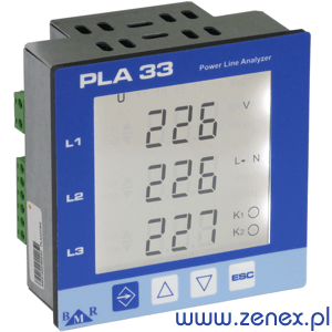
This device converts the digitally (every period of the sinusoid) parameters measured RMS current and voltage three-phase network, according to EN61000-4-30.
At each cycle of the sine wave falls 128 samples used in the calculation. Every second of the analyzer measures 50 samples of currents and voltages,
calculations are displayed and saved to the internal memory registers.
PLA33 type analyzer has 6 internal
Electrical energy meters for energy consumed, produced - active, inductive, and capacitive.
Each electricity meter can be configured as pulse output to other devices.
Interface
RS485 communication with Modbus RTU protocol allows the connection type analyzers: PLA33C, PLA33CM, PLA33IC, PLA33ICM,
PLA33DLC, PLA33DLCM to any Modbus master. The analyzer works with goals Ethernet'owymi
Modbus RTU / Modbus TCP, so there is a possibility of reading devices by a number of peripheral devices at the same time,
such as PLCs, HMI terminals, original software WMD (Power Monitor System), and
any SCADA system.
To gain access to the server, open the following link:
PLA44
Enter the username "admin" and the password "1234".

Optional internal memory is used to store the measured and calculated parameters of the power supply. record
Memory defines the PC. The analyzer can store a sample in the period from 200 ms to 1 hour. The length of the possible
recording depends on the amount of stored parameters. The solution can be used in places where flush current monitoring
and recording systems recording is not possible. Saved parameters are downloaded via a link Modbus RTU.
Analyzer
It has the ability to register the load profile. Records the value of all six of energy at a specific time to the memory.
The period of record is defined between 1 to 60 minutes with a PC via the PMS software.
| Device variant | Clock | 2x Outputs | Max/min | RS485 | RS485 insulation | Flash Memory |
|---|---|---|---|---|---|---|
| PLA33LB | ||||||
| PLA33B | • | • | • | |||
| PLA33CB | • | • | • | • | ||
| PLA33CMB | • | • | • | • | • | |
| PLA33ICB | • | • | • | • | ||
| PLA33ICMB | • | • | • | • | • |
The analyzer has 2 programmable outputs that can be used as an alarm or pulse. Each output has the ability to defining three terms of logic (AND or OR). Optionally, the analyzer can be 24VDC power supply.
| Parameter | L1 | L2 | L3 | ΣL1-3 | Min | Max | Measuring range | Display range | Accuracy |
|---|---|---|---|---|---|---|---|---|---|
| Phase voltage, L - N | • | • | • | • | • | 0 ... 300 V | 0 ... 180 kV | ±0,5 % MR | |
| Interfacial voltage, L - L | • | • | • | • | • | 0 ... 520 V | 0 ... 312 kV | ±0,5 % MR | |
| Frequency | • | • | 40 ... 70 Hz | 40 ... 70 Hz | ±0,2 % MV | ||||
| Current | • | • | • | • | 0,01 ... 6 A | 0 ... 7,5 kA | ±0,5 % MR | ||
| Neutral current | • | • | - | 0 ... 7,5 kA | ±1,5 % MR | ||||
| Power factor | • | • | 0,01ind ... 0,01poj | 0,01ind ... 0,01poj | ±0,5 % MV | ||||
| cosφ | • | • | • | • | 0,01ind ... 0,01poj | 0,01ind ... 0,01poj | ±0,5 % MV | ||
| THDu | • | • | • | • | 0 ... 999 % | 0 ... 999 % | ±1,0 % MR | ||
| THDi | • | • | • | • | 0 ... 999 % | 0 ... 999 % | ±1,0 % MR | ||
| Odd harmonics U | • | • | • | • | 0 ... 999 % | 0 ... 999 % | ±1,0 % MR | ||
| Odd harmonics I | • | • | • | • | 0 ... 999 % | 0 ... 999 % | ±1,0 % MR | ||
| Moc pozorna S | • | • | • | • | 0 ... 1,8 kVA | 0 ... 648 MVA | ±1,0 % MR | ||
| Moc czynna P | • | • | • | • | 0 ... 1,8 kW | 0 ... 648 MW | ±1,0 % MR | ||
| Moc bierna Q | • | • | • | • | 0 ... 1,8 kVAr | 0 ... 648 MVAr | ±1,0 % MR | ||
| Apparent power ΣS | • | • | 0 ... 5,4 kVA | 0 ... 999 MVA | ±1,0 % MR | ||||
| Active power ΣP | • | • | 0 ... 5,4 kW | 0 ... 999 MW | ±1,0 % MR | ||||
| Reactive power ΣQ | • | • | 0 ... 5,4 kVAr | 0 ... 999 MVAr | ±1,0 % MR | ||||
| Active energy | • | 0 ... 9.999.999 kWh | 0 ... 9.999.999 kWh | Class 1 * | |||||
| Reactive energy L | • | 0 ... 9.999.999 kVArh | 0 ... 9.999.999 kVArh | Class 1 * | |||||
| Reactive energy C | • | 0 ... 9.999.999 kVArh | 0 ... 9.999.999 kVArh | Class 1 * |
| Supply voltage | 230VAC, lub 24VDC (+10%,-15%) |
|---|---|
| Frequency | 45 ... 65 Hz |
| Measuring voltage L-N | 0 ... 300 VAC |
| Measuring current | 0,01 ... 5,3 A |
| Accuracy measurement of U and I | 0,5% |
| Power consumption | 1,5 VA |
| Number of outputs | 2 |
| Type of outputs | NPN transistor |
| Maximum output load capability | 24 VDC / 100 mA |
| Available voltage transformer | 1 ... 1500 |
| Current gear unit available | 1 ... 1500 |
| Communication interface | RS485 |
| The communication protocol | Modbus RTU |
| Communication speed | 9600 ... 115 000 Bd |
| Internal memory | 512 MB Flash |
| Working ambient temperature | -30°C ... +70°C |
| Front panel dimensions | 96 mm x 96 mm |
| Panel cutout dimensions | 91 mm x 91 mm |
| Site depth | 50 mm |
| Weight | 0,5 kg |
| Protection degree | IP20 back panel / IP54 front |
PLA34
 The power quality analyser PLA34 is designed according to norm EN 61000-4-30 to fit the class S of power quality analyser.
PLA34 is built on a 32 bit RISC processor that provides sufficient processing capabilities for real-time measurement and
calculation of all parameters values.
The power quality analyser PLA34 is designed according to norm EN 61000-4-30 to fit the class S of power quality analyser.
PLA34 is built on a 32 bit RISC processor that provides sufficient processing capabilities for real-time measurement and
calculation of all parameters values.
Measuring method
Device digitizes voltage and current in 4 phases continually with sampling rate of 40 kHz. Measurement is synchronized by very precise internal clock with NTP synchronization strictly according EN 61000-4-30 class S norm. Measured and calculated values are stored in the internal flash memory for downloading by software for evaluation of power quality according to EN 50160 norm. Events and transients are available with detaile information on the device screen as well as on PC in monitoring software in web browser thanks to internal web-server.
Flicker
PLA34 measures short term and long term flicker strictly according to the standard EN 61000-4-15.
Harmonics measurement
PLA34 measures particular harmonics of U, I, P, Q up to 65th harmonics as well as group of harmonics and interharmonics of U and I in all 4 phases. THDU is measured for phase voltages and also for line voltages. THDI is measured for all 4 current inputs.
Display
PLA34 has clear LCD display to show most interesting parameters and let make the minimum important settings of the instrument. More measured parameters and advanced setting is available from software PMS.
Web server
Device has embedded web server for remote monitoring of the PLA34 instrument over the Internet.
To visit the real instrument web-server follow the link:
PLA44
Enter the username "admin" and password "1234" to access the instrument web server.


| Parameter | L1 | L2 | L3 | L4 | L1-2 | L2-3 | L3-1 | ΣL1-3 | ΣL1-4 | Max | Min | AVG | MaxAVG | Measuring | Display | Accuracy |
|---|---|---|---|---|---|---|---|---|---|---|---|---|---|---|---|---|
| Phase voltage, L - N | • | • | • | • | • | • | • | • | 10 ... 600 V | 1 V ... 1 MV | 0,1% | |||||
| Interfacial voltage, L - L | • | • | • | • | • | • | • | 18 ... 1000V | 0 ... 1 MV | 0,1% | ||||||
| Frequency | • | • | • | • | • | 40 ... 70 Hz | 40 ... 70 Hz | 10 mHz | ||||||||
| Current | • | • | • | • | • | • | • | 0,001 ... 8,5A | 1 mA ... 1 MA | 0,2% | ||||||
| Cosφ | • | • | • | • | • | 0,01L ... 0,01C | 0,01L ... 0,01C | 0,5% | ||||||||
| Power factor | • | • | • | • | • | • | • | 0,01L ... 0,01C | 0,01L ... 0,01C | 0,5% | ||||||
| THDU L-N | • | • | • | • | • | • | • | • | 0 ... 999% | 0 ... 999% | 1% | |||||
| THDU L-L | • | • | • | • | • | • | • | 0 ... 999% | 0 ... 999% | 1% | ||||||
| THDI | • | • | • | • | • | • | • | • | 0 ... 999% | 0 ... 999% | 1% | |||||
| Harmonics U | • | • | • | • | • | • | • | • | 0 ... 999% | 0 ... 999% | Class 1 | |||||
| Group of interharm. U | • | • | • | • | 0 ... 999% | 0 ... 999% | Class 1 | |||||||||
| Group of harm. U | • | • | • | • | 0 ... 999% | 0 ... 999% | Class 1 | |||||||||
| Harmonics P | • | • | • | • | 0 ... 999% | 0 ... 999% | Class 1 | |||||||||
| Harmonics Q | • | • | • | • | 0 ... 999% | 0 ... 999% | Class 1 | |||||||||
| Harmonics I | • | • | • | • | 0 ... 999% | 0 ... 999% | Class 1 | |||||||||
| Group of interham. I | • | • | • | • | 0 ... 999% | 0 ... 999% | Class 1 | |||||||||
| Groupd of harm. I | • | • | • | • | 0 ... 999% | 0 ... 999% | Class 1 | |||||||||
| Short term flicker | • | • | • | • | • | 0,4 ... 10,0 Pst | 0,4 ... 10,0 Pst | Class A | ||||||||
| Long term flicker | • | • | • | • | • | 0,4 ... 10,0 Plt | 0,4 ... 10,0 Plt | Class A | ||||||||
| Undervoltage | • | • | • | • | • | • | • | • | • | • | • | 0 ... 100% | 0 ... 100% | 0,2% | ||
| Overvoltage | • | • | • | • | • | • | • | • | • | • | • | 0 ... 100% | 0 ... 100% | 0,2% | ||
| Unbalance U | • | • | • | • | 0 ... 100% | 0 ... 100% | 0,15% | |||||||||
| N displacement | • | • | • | • | 10 ... 600 V | 0 ... 1 MV | 0,2% | |||||||||
| K factor | • | • | • | • | ||||||||||||
| Unbalance I | • | • | • | • | 0,5% | |||||||||||
| Transients | • | • | • | • | 25 µs | |||||||||||
| Events | • | • | • | • | 10 ms | |||||||||||
| Ripple control signal | • | • | • | • | • | • | • | • | • | • | • | |||||
| Active power ΣP | • | • | • | • | • | • | • | 0 ... 15,3 kW | 0 ... 999 GW | 0,2% | ||||||
| Apparent power ΣS | • | • | • | • | • | • | • | 0 ... 15,3 kvar | 0 ... 999 Gvar | 0,2% | ||||||
| Reactive power ΣQ | • | • | • | • | • | • | • | 0 ... 15,3 kVA | 0 ... 999 GVA | 0,2% | ||||||
| Distortion power ΣSP | • | • | • | • | • | • | • | 0,2% | ||||||||
| Active energy | • | • | • | • | 0 ... 999 GWh | 0 ... 999 GWh | 0,2% | |||||||||
| Reactive energy L | • | • | • | • | 0 ... 999 Gvarh | 0 ... 999 Gvarh | 0,2% | |||||||||
| Reactive energy C | • | • | • | • | 0 ... 999 Gvarh | 0 ... 999 Gvarh | 0,2% |
| Supply voltage | 230 VAC (+10%,-15%), 50/60 Hz |
| Power consumption | 2 VA |
| Measuring voltage L-N | 10 ... 600 V |
| Measuring voltage L-L | 18 ... 1000 V |
| Direct current measurement range | 1 mA ... 8,5 A (3P + N) |
| Available voltage transformer | 1 ... 750tyś |
| Current gear unit available | 1 ... 750tyś |
| Frequency | 40 ... 70 Hz |
| Measurement in networks | four-pole (3P+N) |
| Grid type | TN, TT, IT |
| Clock | < 1 s na dzień |
| Sampling frequency | 40 kHz |
| Transients | 25 µs |
| Events trigger | 10 ms |
| Display | VGA LCD |
| Memory | 1GB flash |
| Communication protocol | Modbus RTU, Modbus TCP, SNTP, HTTP, FTP |
| Communication interface | RS485, USB, Ethernet |
| Dimensions | 96 x 96 x 70 mm |
| Weight | 1000 g |
| Related standards | IEC 61000-4-30 Class S, IEC 61000-4-7, IEC 61000-4-15, IEC61557-12 |

Main features
- 4 quadrant measurement
- EN 61000-4-30 Class S
- 4 current inputs, 3 voltage inputs
- Harmonics and inter-harmonics to EN 61000-4-7
- Flicker measurement (jitter) EN 61000-4-15
- Sampling frequency 40Hz
- RS485, Ethernet, USB
- Web Server
PLA44
 The power quality analyzer PLA44 is designed according to norm EN 61000-4-30 class A for measurement of electrical
parameters in LV and MV systems. PLA44 is built on a 32 bit RISC processor that provides sufficient processing capabilities
for real-time measurement and calculation of all parameters values.
The power quality analyzer PLA44 is designed according to norm EN 61000-4-30 class A for measurement of electrical
parameters in LV and MV systems. PLA44 is built on a 32 bit RISC processor that provides sufficient processing capabilities
for real-time measurement and calculation of all parameters values.
Device description
Device digitizes voltage and current in 4 phases continually with sampling rate of 40 kHz. Measurement is synchronized by very precise internal clock with NTP synchronization strictly according EN 61000-4-30 class A norm. Measured and calculated values are stored in the internal flash memory for downloading by software for evaluation of power quality according to EN 50160 norm. Events and transients are available with detail information on the device screen as well as on PC or web browser thanks to build-in web-server.
Flicker
Short term and long term flicker is calculated statistically and strictly according to the norm EN 61000-4-15 and it meets the class A.
Harmonics measurement
PLA44 measures particular harmonics of U, I, P, Q up to 65th harmonics as well as group of harmonics and inter-harmonics of U and I in all 4 phases. THDU is measured for phase voltages and also for line voltages. THDI is measured for all 4 current inputs.
Display
Full graphic TFT display with VGA (800 x 600 px) resolution


Web server
Device has embedded web server for remote monitoring of the PLA44 instrument over the Internet.
To visit the real instrument web-server follow the link:
PLA44
Enter the user-name "admin" and password "1234" to access the instrument web server.
| Parameter | L1 | L2 | L3 | L4 | L1-2 | L2-3 | L3-1 | ΣL1-3 | ΣL1-4 | Max | Min | AVG | MaxAVG | Measuring | Display | Accuracy |
|---|---|---|---|---|---|---|---|---|---|---|---|---|---|---|---|---|
| Phase voltage, L-N | • | • | • | • | • | • | • | • | 10 ... 600 V | 1 V ... 1 MV | 0,1% | |||||
| Interfacial voltage, L-L | • | • | • | • | • | • | • | 18 ... 1000V | 0 ... 1 MV | 0,1% | ||||||
| Frequency | • | • | • | • | • | 40 ... 70 Hz | 40 ... 70 Hz | 10 mHz | ||||||||
| Current | • | • | • | • | • | • | • | • | • | 0,001 ... 8,5A | 1 mA ... 1 MA | 0,2% | ||||
| Cosφ | • | • | • | • | • | 0,01L ... 0,01C | 0,01L ... 0,01C | 0,5% | ||||||||
| Power factor | • | • | • | • | • | • | • | 0,01L ... 0,01C | 0,01L ... 0,01C | 0,5% | ||||||
| THDU L-N | • | • | • | • | • | • | • | • | 0 ... 999% | 0 ... 999% | 1% | |||||
| THDU L-L | • | • | • | • | • | • | • | 0 ... 999% | 0 ... 999% | 1% | ||||||
| THDI | • | • | • | • | • | • | • | • | 0 ... 999% | 0 ... 999% | 1% | |||||
| Harmonics U | • | • | • | • | • | • | • | • | 0 ... 999% | 0 ... 999% | Class 1 | |||||
| Group of interharm. U | • | • | • | • | 0 ... 999% | 0 ... 999% | Class 1 | |||||||||
| Group of harm. U | • | • | • | • | 0 ... 999% | 0 ... 999% | Class 1 | |||||||||
| Harmonics P | • | • | • | • | 0 ... 999% | 0 ... 999% | Class 1 | |||||||||
| Harmonics Q | • | • | • | • | 0 ... 999% | 0 ... 999% | Class 1 | |||||||||
| Harmonics I | • | • | • | • | 0 ... 999% | 0 ... 999% | Class 1 | |||||||||
| Group of interham.I | • | • | • | • | 0 ... 999% | 0 ... 999% | Class 1 | |||||||||
| Groupd of harm. I | • | • | • | • | 0 ... 999% | 0 ... 999% | Class 1 | |||||||||
| Short term flicker | • | • | • | • | • | 0,4 ... 10,0 Pst | 0,4 ... 10,0 Pst | Class A | ||||||||
| Long term flicker | • | • | • | • | • | 0,4 ... 10,0 Plt | 0,4 ... 10,0 Plt | Class A | ||||||||
| Undervoltage | • | • | • | • | • | • | • | • | • | • | • | 0 ... 100% | 0 ... 100% | 0,2% | ||
| Overvoltage | • | • | • | • | • | • | • | • | • | • | • | 0 ... 100% | 0 ... 100% | 0,2% | ||
| Unbalance U | • | • | • | • | 0 ... 100% | 0 ... 100% | 0,15% | |||||||||
| N displacement | • | • | • | • | 10 ... 600 V | 0 ... 1 MV | 0,2% | |||||||||
| K factor | • | • | • | • | ||||||||||||
| Unbalance I | • | • | • | • | 0,5% | |||||||||||
| Transients | • | • | • | • | 25 µs | |||||||||||
| Events | • | • | • | • | 10 ms | |||||||||||
| Ripple control signal | • | • | • | • | • | • | • | • | • | • | • | |||||
| Active power ΣP | • | • | • | • | • | • | • | • | • | 0 ... 15,3 kW | 0 ... 9999 GW | 0,2% | ||||
| Apparent power ΣS | • | • | • | • | • | • | • | • | • | 0 ... 15,3 kVA | 0 ... 9999 GVA | 0,2% | ||||
| Reactive power ΣQ | • | • | • | • | • | • | • | • | • | 0 ... 15,3 kvar | 0 ... 9999 Gvar | 0,2% | ||||
| Active energy | • | • | • | • | 0 ... 9999 GWh | 0 ... 9999 GWh | 0,2% | |||||||||
| Reactive energy L | • | • | • | • | 0 ... 9999 Gvarh | 0 ... 9999 Gvarh | 0,2% | |||||||||
| Reactive energy C | • | • | • | • | 0 ... 9999 Gvarh | 0 ... 9999 Gvarh | 0,2% | |||||||||
| Temperature | • | • | • | • | 1°C |
| Supply voltage | 230 VAC (+10%,-15%) |
| Power consumption | 5 VA |
| Measuring voltage L-N | 10 ... 600 VAC |
| Measuring voltage L-L | 18 ... 1000 VAC |
| Measuring current (without CT) | 1 mA ... 8,5 A |
| Frequency | 40 ... 70 Hz |
| Clock accuracy | < 1 s per day |
| Number of output/input | 2 (+ expansions module) |
| Voltage and current CT | 1 ... 750 000 |
| Sampling rate | 40 kHz |
| Events trigger | 10 ms |
| Transients trigger | 25 µs |
| Data memory | 1 GB flash |
| Display | TFT VGA 5,6" |
| Temperature input | NTC 10kΩ / 25°C |
| Communication interface | RS485, LAN, USB |
| Communication protocol | Modbus RTU, Modbus TCP, SNTP, HTTP, FTP |
| Working ambient temperature | -25°C ... +70°C |
| Dimensions | 144 x 144 mm |
| Weight | 1350 g |
| Protection degree | IP20 back panel / IP54 front panel |
| Related standards | IEC 61000-4-30 class A, IEC 61000-4-7, |
| IEC 61000-4-15, IEC61557-12 |

Main features
- 4 quadrant measurement
- EN 61000-4-30 Class A
- 4 current inputs, 4 voltage inputs
- Harmonics and inter-harmonics to EN 61000-4-7
- Flicker measurement (jitter) EN 61000-4-15
- Sampling frequency 40Hz
- RS485, Ethernet, USB
Modules (contactors) thyristor capacitor - type of CTU
Since 2008 our company is main importer of CTU thyristor switching modules, produced by Czech company BMR.
| BMRXCTU34001024 | Thyristor switching module 10/18kVar/400VAC (15A) for capacitive load switching, control voltage 24VDC |
| BMRXCTU34003024 | Thyristor switching module 30/51kVar/400VAC (42A) for capacitive load switching, control voltage 24VDC |
| BMRXCTU34005024 | Thyristor switching module 50/90kVar/400VAC (75A) for capacitive load switching, control voltage 24VDC |
Thyristor switching modules CTU03 and CTU33 are designed for dynamic and hybrid PFC based on three-phase capacitors. CTU03 modules have special semiconductor switcher in each phase. Together with controllers FCR and GCR range they can reach the best possible speed of reconnection up to 25 operations per 1 second. Special construction of the module solves voltage discharging problem so the three-phase capacitor can be switched again immediately after disconnection without prior discharging. Switching is realized within 10 ms from receiving the signal from PF controller.

Thyristor switching modules CTU are constructed for switching of LC circuits with prevailing capacitive part (detuned compensation stages). Advantage of CTU modules comparing to the classic contactor switching of capacitor stages is immediate capacitor connection without its previous discharging. This is possible thanks to special construction which assures that capacitor is ready for another connection immediately after its previous disconnection. Switching of capacitor is realized at the moment when the difference between the capacitor voltage and system voltage before the switching element is equal to zero. From this feature comes another important advantage and this is significant current surges reduction. Current surges are causing disturbances which can affect proper running of electronic devices and can severely damage and even destroy them. Further more, lifetime of capacitors is increased, because only nominal current flows through the circuit. For the protection of power switching element against current peaks (di/dt) it is necessary to connect in the series with module also inrush inductor.
Temperature protection
Inside the CTU03 and CTU33 module aluminum cooler is installed temperature sensor which is used for protection of semiconductors against damage by high temperature. Temperature level is set on 80°C.
Forced ventilation
CTU03-400-50 and CTU03-400-72 have a ventilator for forced ventilation of aluminum coller. The same for variant CTU33. Ventilator is started automatically when temperature of cooler rise over the defined level.

- Product Data Sheet PLA 33
Product Data Sheet PLA 33
- Product Data Sheet PLA 44
Product Data Sheet PLA 44
- Installation Manual and service of PLA 33
Installation Manual and service of PLA 33
- Installation Manual and service of PLA 34
- Installation Manual and service of PLA 44
Installation Manual and service of PLA 44
- Modbus registers
Modbus registers
- PMS Software (Power Monitor System)
PMS Software (Power Monitor System)
- CE Declaration PLA33
CE Declaration PLA33
- CE Declaration PLA34
CE Declaration PLA34
- CE Declaration PLA44
CE Declaration PLA44
- Certificate of Calibration PLA33
Certificate of Calibration PLA33
- Certificate of Calibration PLA34
Certificate of Calibration PLA34
- Certificate of Calibration PLA44
Certificate of Calibration PLA44
- PLA 34 Firmware Update
PLA 34 Firmware Update
- PLA 44 Firmware Update
PLA 44 Firmware Update
- Manual PMS program
Manual PMS program
- PLA33 Modbus registers
PLA33 Modbus registers